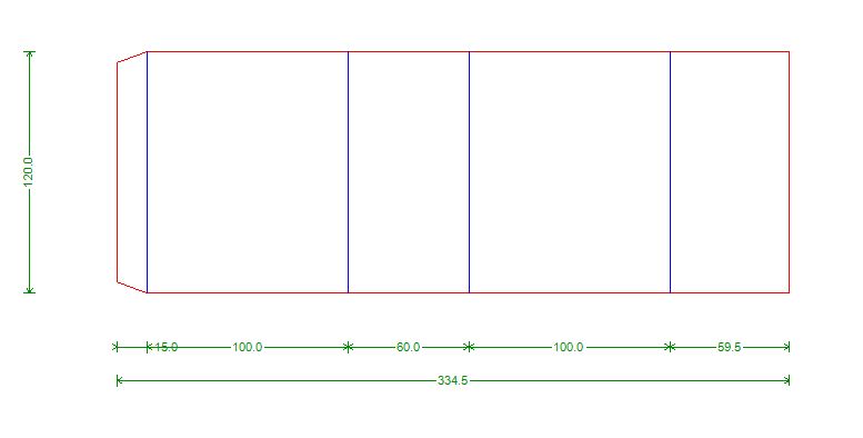
In the section we will introduce the parametric design feature in Picador to create your own standard models in PackLib:
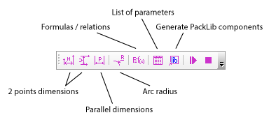
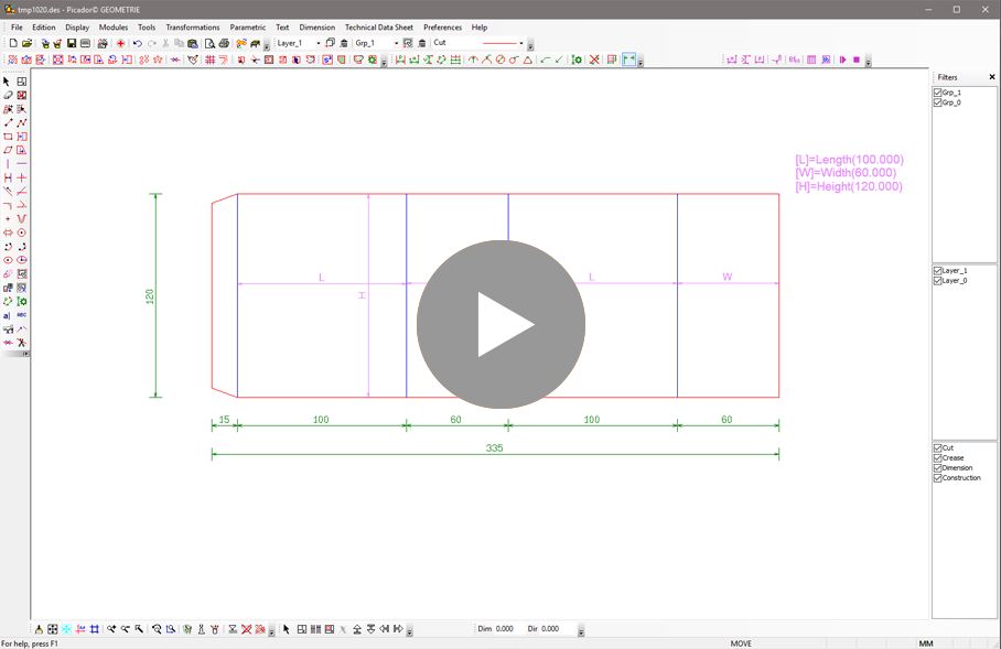
To create parametric design, it’s happen in Picador 2D, on any model you have access to the parametric tool bar. Those tools allow you to add purple dimensions on your drawing and define each dimension as a parameter (basically on or two letters). Those parameter will be editable in PackLib and allows to change the defined dimensions.


After discribing some parametric dimensions, use the  Edit parameter function to discribe the parameters and add it in the document.
Then use the  "Generate a parametric component" , Picador convert the drawing into a component (code) that will be usable in other application, such Packlib, ERP...,
clic on generate to get a visual of the new parametric model, and the interface. Play with the parameter to check if every thing is working properly.


