
")
")
")
This part is dedicated to basic drawing features with Picador Geometry. For more information please read the User Guide Geometry Picador. (Help/User Guide)
Toolbars:
All the functions and drawing tools are grouped in the form of icons in toolbars, which appear around the software window.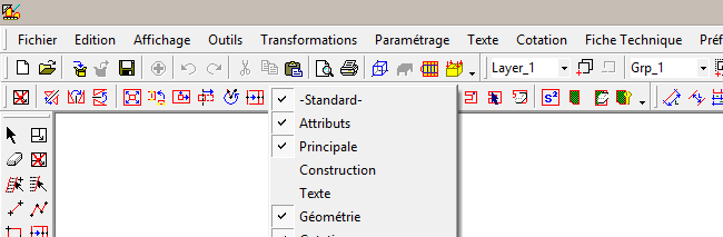
 on some Picador skin) on the letf of each toolbar to drag it to another place.
Basic drawing: Drawing lines


1 - Connect with the link assistants visible on the side of the mouse cursor:
![]() The attachment point is the extremity of a segment or arc:
The attachment point is the extremity of a segment or arc:

![]() The attachment point is the midpoint of a segment:
The attachment point is the midpoint of a segment:

![]() The attachment point is the intersection of two segments or construction lines:
The attachment point is the intersection of two segments or construction lines:

 Join with a segment when orthogal to it:
 Join an vertical segment horizontaly aligned to a point: / Join an horizontal segment verticaly aligned to a point:
 Connect with the center of a circle:
2- Input the point coordinates, defining the position of the point on the X and Y axis:
To open the tab, press X or Y key or any digit (0,1,2,3,...).
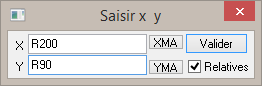
From this panel you define the coordinates of a point, for a 2pts segment, you may click the first one on the page and define the second with coordonate.
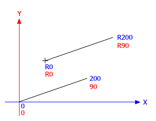
Coordonate could be define from the previous anchor point by adding "R" or "r" before the value; It's relative coordonates:

3- Input the size and the direction of the segment:
Click the starting point of the segment, then to open the panel, press D key on the keyboard.
The first panel is to set the dimension of the segment, the second is to set the direction or angle:

The angle is define according anti-clockwise direction (trigonometrical) : 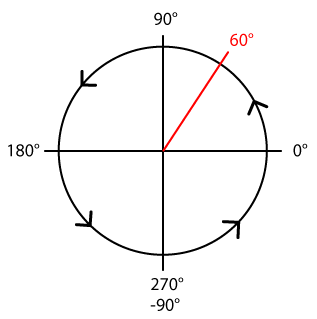
Basic drawing: interactions
Select elements:
Use selection arrow ![]() or windowed selection
or windowed selection ![]() to select one or multiple elements. Selected entities change color to black (or white if the background color is black):
to select one or multiple elements. Selected entities change color to black (or white if the background color is black):

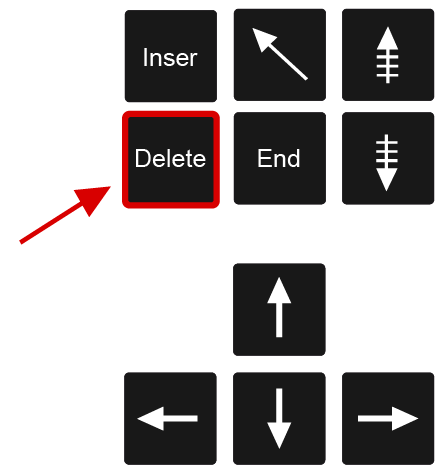
Delete elements:

Navigation:
To move the view in the document:
 or press the wheel of your mouse (button 3) and drag the page.
To Zoom forward and backward:
Roll forward or backward the mouse wheels.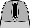
Tip: Point with the cursor the area you want to look closer, then use the wheel to zoom, the view fit to the cursor location. It may seem tricky at the beginning but you can move and zoom in the same time
The type of line selections:
The vast majority of designs made with Picador are plans of packaging or cardboard displays. The plan which are drawn with Picador represent the packaging 2D design, and are usable for production. It's directly the plan for the diecutting tool and the process for the cutting table. Therefore the pens of different colors directly define type of lines that will be used on the cutting process.
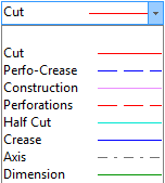 |
The line color is define by the drop-down list on the top of the Picador window.All the entities are drawn of the color of this attribut box. Cut line: the board will be cut following those lines. Crease line: the board will be process to make a fold along those lines.
|

Basic drawing: construction lines
The construction lines or guides are a very important element of our structural drawing methode. Placing guides help you to define your design and once in place, the guides create attachment points to build your drawing. Here is the main tools to place them, reproduce the use of each tool you see in the video.


Our first model:
It's time to implement what we seen by creating our first model. follow the steps detailed in the next videos:
Draw a 200x100mm rectangle using multi-segment ![]() tool and XY coordonate:
tool and XY coordonate:


Don't hesitate to refer to this chapter if you feel a bit lost with the drawing features during the next chapters.